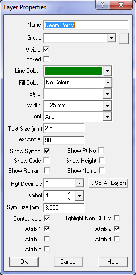
Layer Properties
This dialog box allows the user to alter any of the properties or attributes for the selected layer.
Name
Enter the name of the layer. Only certain alphanumeric characters can be used. The name can contain spaces
if necessary though the spaces will not be used when exporting to DXF files.
The legal characters are: A-Z,a-z,0-9,+-_()[]{}<> .
You can use a plus sign, minus sign, underscore, space, full stop
Group
Select the group for this layer. Layers can be grouped together and the group of layers manipulated
together.
Visible
This controls whether this layer is displayed on the screen. When checked, the layer will be displayed.
This checkbox can also be altered in the main layers dialog box.
Locked
This controls whether the layer is locked or not. You cannot change any items such as points, strings
or text that are on a locked layer.
Line Colour
Select the colour from the drop down list. The colour selected will be used for all items on the layer
(points, strings, text etc) except if the item has a particular colour assigned to it. To make an
item use the layer colour, specify the 'By Layer' attributes in the item properties. Click here
for Colour chart.
Fill Colour
Select the Fill colour from the drop down list. The colour selected will be used for 'colouring in'
all closed strings on the layer except if the item has a particular colour assigned to it.
To make an item use the layer colour, specify the 'By Layer' attributes in the item properties.
Click here for Colour chart.
Line Style
The line style can be selected from the drop down list. There are a number of standard Windows
line styles 1-15 followed by some special surveying line styles. Note that if the line thickness
is greater than 0.5mm, the selected line style may not be displayed due to limitations in the
Windows drawing system.
Width
The line width or thickness can be selected from the drop down list. Note that if the thickness
is greater than 0.5mm, the selected line style may not be displayed due to limitations in the
Windows drawing system.
Font
Select the required Font from the list. The program can only offer those fonts installed in
the Windows font system.
Text Size
Enter the required text size in mm. Items which have the 'By Layer' attribute will use this
text height.
Text Angle
Enter the bearing of the text as a Survey bearing (i.e. 0 is vertically up the page.).
Show Symbol
Click this check box to display the symbol for each point on the layer.
Show Pt Number
Click this check box to display the point number for each point on the layer.
Show Code
Click this check box to display the code for each point on the layer.
Show Height
Click this check box to display the height (RL) for each point on the layer.
Hgt Decimals
When the height is displayed for a point, this field controls the number of decimal places displayed.
Set All Layers
This option will force all other layers in the job to have the same number of decimal places
as selected here.
Symbol
Select the symbol to be displayed at the point.
Symbol Size
Enter the symbol size in mm for the symbol to be displayed. Note: the actual drawn size will
depend on the job plot scale.
Contourable
Tick this box to make all points on this layer contourable.
Note: Non contourable points (unticked) will not be used to form triangles (TIN, DTM)
| Point Layer | Point | Used in Triangles |
| Contourable | Contourable | Yes |
| Contourable | Non Contourable | No |
| Non Contourable | Contourable | No |
| Non Contourable | Non Contourable | No |
Att1, Att2...
These tick boxes control the display (and DXF export) of Point extra attributes.
...Display
Tick this box to highlight Non-contourable points with a purple mark.